
Selecting a display for semiconductor equipment is not simply a matter of choosing a screen size and asking for a quotation. The LCD becomes part of the machine’s operating interface, mechanical structure, electrical system, software environment, maintenance procedure, and long-term spare-parts strategy.
A display that performs well on an engineer’s desk may behave differently after it is installed beside switching power supplies, motors, motion controllers, illumination systems, vacuum components, and other electrical subsystems. The final enclosure may also increase operating temperature, change touchscreen grounding, create reflections, or place the screen outside its best viewing direction.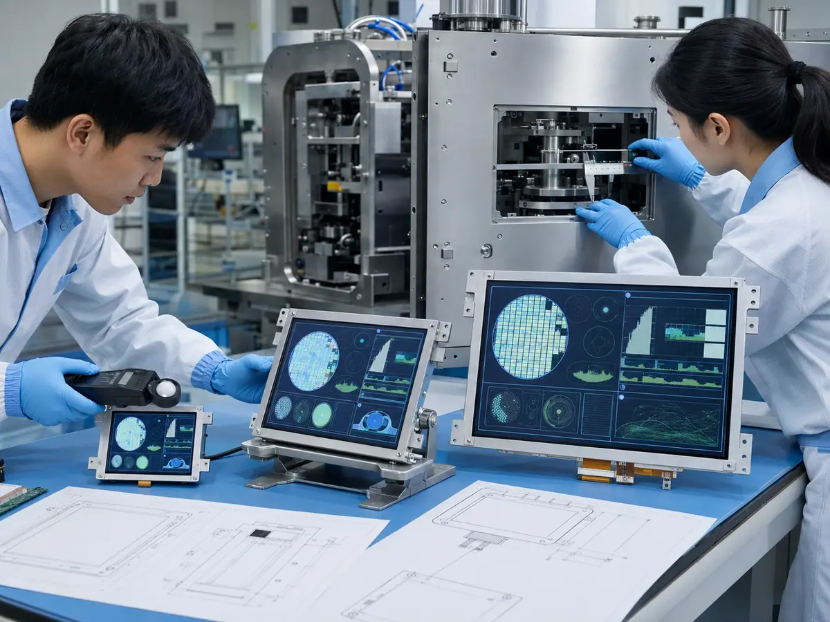
From my experience with industrial LCD projects, the most successful semiconductor display selections begin with the operator workflow rather than a panel datasheet. Engineers first determine what information must be shown, how the user will interact with the equipment, where the display will be installed, and how long the machine must remain supportable. Only then should they select the LCD technology, size, resolution, brightness, touchscreen, interface, and mechanical structure.
This engineering sequence prevents a common problem: selecting a technically impressive display that does not fit the software, enclosure, operator position, or equipment lifecycle.
Quick Answer: Engineers select displays for semiconductor machines by defining the HMI function, software layout, viewing distance, installation space, operating temperature, lighting, touch requirements, electrical interface, reliability target, and equipment lifecycle. They then compare LCD size, resolution, aspect ratio, viewing technology, brightness, contrast, surface treatment, touchscreen type, controller compatibility, mechanical dimensions, and long-term availability. Final approval should be based on testing with the actual equipment rather than datasheet comparison alone.
The display requirement for a basic process-control panel is different from the requirement for a wafer inspection station. A maintenance terminal may prioritize glove operation and serviceability, while an image-review monitor may prioritize resolution, grayscale separation, viewing stability, and reflection control.
There is therefore no universally correct semiconductor display. The correct choice is the one that meets the machine’s real operational and lifecycle requirements without adding unnecessary cost or integration risk.
Claim: Semiconductor display selection should be treated as a system-level engineering process. The LCD panel, touchscreen, controller, cover glass, enclosure, software, power design, and lifecycle plan must be evaluated together.
1. What Requirements Should Engineers Define Before Selecting a Display?
The first stage should produce a written display requirement. Without this document, different teams may evaluate the screen according to different priorities. Mechanical engineers may focus on dimensions, software engineers on resolution, purchasing teams on price, and operators on usability. A complete requirement brings these considerations together.
What Is the Display’s Primary Function?
Engineers should identify whether the display will be used for basic machine control, process monitoring, wafer handling, recipe management, inspection review, metrology, alarm diagnosis, maintenance, or remote engineering analysis.
A basic equipment HMI may show buttons, status indicators, numerical values, process diagrams, and alarm messages. It normally requires dependable readability and touch operation, but it may not need exceptionally high resolution or specialized color performance.
A wafer inspection display may present wafer maps, defect images, coordinate data, classification results, histograms, and several software windows at the same time. This type of interface benefits from higher resolution, wider viewing angles, stable grayscale, and lower reflection.
A service display may need to remain readable from an unusual angle while a technician works inside the machine. It may also require operation with gloves or a stylus. These requirements directly affect LCD and touchscreen selection.
The reasons semiconductor equipment depends on dedicated industrial displays are explained in Why Do Semiconductor Machines Require Industrial LCDs?.
Who Will Operate the Display?
The user may be a production operator, process engineer, equipment engineer, maintenance technician, or field-service technician. Each role uses the interface differently.
Production operators generally need simple navigation, clear machine status, controlled recipe selection, and unmistakable alarm messages. Process engineers may require detailed charts, images, statistics, and parameter comparisons. Service technicians need access to diagnostic pages, communication states, calibration data, and subsystem controls.
The display should support the most demanding intended workflow without making routine production operation unnecessarily complicated. Software can provide role-based access, but the screen must still have enough resolution and physical area for the required information.
Where Will the Display Be Installed?
The engineer should document mounting height, viewing distance, viewing direction, orientation, available enclosure space, cable path, ventilation, and service access. A panel mounted above eye level may require a different viewing technology from a screen mounted directly in front of a seated operator.
The internal enclosure temperature should be measured or estimated. A controlled cleanroom temperature does not guarantee a cool display compartment. Heat from the computer, controller board, power supply, backlight, and nearby machine subsystems can raise the temperature behind the screen.
Installation location also affects mechanical construction. A flush front may require custom cover glass and a gasket. An adjustable arm may require stronger cable retention and resistance to repeated movement. A display installed close to process equipment may need better grounding and electromagnetic-noise control.
What Environmental Conditions Must Be Considered?
Important conditions include operating temperature, storage temperature, humidity, vibration, electrostatic discharge, electromagnetic interference, cleaning frequency, cleaning chemicals, glove use, and expected daily operating hours.
The display panel alone does not determine cleanroom suitability or ingress protection. The final cover glass, bezel, gasket, housing, cable entries, and installation method create the equipment-level protection.
If cleaning agents will contact the front surface, the engineer should verify compatibility with the glass coating, printing, adhesive, gasket, and touchscreen structure. A surface may look acceptable during sample evaluation but deteriorate after repeated cleaning cycles.
What Lifecycle and Service Requirements Must Be Defined?
The equipment manufacturer should define the planned production period, expected service life, spare-parts period, annual demand, and acceptable replacement strategy. A display used in a short laboratory project can be sourced differently from one used across a large installed equipment fleet.
Engineers should also decide whether the field-replaceable item will be the LCD panel, the LCD and touchscreen assembly, or a complete monitor. This decision affects spare inventory, service training, replacement time, and future qualification work.
| Requirement Area | Questions to Define | Display Parameters Affected |
|---|---|---|
| Application | Control, inspection, metrology, maintenance, or remote review? | Size, resolution, color, contrast, response |
| Operator | Viewing position, gloves, input method, user role? | Viewing angle, touchscreen, button size |
| Installation | Space, orientation, ventilation, mounting, cable access? | Outline, thickness, interface, structure |
| Environment | Temperature, cleaning, noise, vibration, operating hours? | Temperature range, glass, touch, reliability |
| Lifecycle | Production period, service period, annual demand, spare strategy? | Panel family, availability, replacement design |
Claim: Engineers should define display function, users, installation, environment, software, service strategy, and lifecycle before comparing LCD models. A clear requirement prevents technical teams from selecting the screen according to isolated specifications.
2. How Should LCD Size, Resolution, and Optical Performance Be Selected?

After the system requirement has been defined, engineers can translate it into measurable LCD specifications. Size and brightness are important, but they should not be evaluated independently from resolution, viewing distance, software scaling, surface reflection, and image content.
How Should Screen Size Be Determined?
Screen size should be based on the information shown, the normal viewing distance, the operator’s reach, and the available enclosure opening. A larger screen can improve readability, but it also increases equipment width, power consumption, cover-glass cost, and mechanical load.
Compact local controls frequently use displays in the 7-inch to 12.1-inch range. General equipment HMIs commonly use 10.1-inch, 12.1-inch, 15-inch, or 15.6-inch panels. Inspection and engineering interfaces may use 17-inch, 19-inch, 21.5-inch, 23.8-inch, 27-inch, or larger screens.
These are typical application ranges rather than fixed rules. A well-designed 10.1-inch interface can be easier to operate than a poorly organized 15.6-inch interface. Software layout and physical installation should remain the deciding factors.
How Should Resolution and Aspect Ratio Be Selected?
Resolution determines how much graphical information can be shown and how sharply text, wafer maps, icons, and images can be rendered. However, a higher resolution is only beneficial when the software and operator can use it effectively.
Legacy semiconductor machines often use 4:3 or 5:4 displays with resolutions such as 1024 × 768 or 1280 × 1024. Newer equipment increasingly uses 16:9 or 16:10 screens, including 1280 × 800 and 1920 × 1080.
When replacing an existing display, maintaining the original resolution and aspect ratio can prevent software distortion. Replacing a 15-inch 4:3 screen with a 15.6-inch widescreen may appear reasonable based on diagonal size, but the active area and interface layout are substantially different.
For new equipment, engineers should create or test the HMI at the proposed native resolution. Operating-system scaling should not be assumed to correct every software issue. Fixed-size controls, legacy applications, and specialized inspection software may not scale correctly.
When Is High Resolution Necessary?
High resolution is valuable when the interface must show several information areas simultaneously. Wafer inspection systems may need to display a wafer map, defect image, coordinate information, classification data, charts, and equipment status within one workspace.
Higher pixel density can improve image and text detail, but it can also make interface controls too small. Engineers should evaluate the screen from the intended viewing distance and with the actual software.
The role of resolution and image presentation in inspection equipment is discussed in How Do LCD Displays Improve Wafer Inspection Systems?.
How Much Brightness Is Required?
Many indoor semiconductor-equipment displays can operate effectively at approximately 300 to 500 nits, depending on room lighting, cover glass, viewing distance, and interface colors. Higher brightness may be necessary when the screen is installed under strong overhead lighting or behind reflective protective glass.
Brightness should not be increased automatically. A brighter backlight produces more heat, consumes more power, and may accelerate brightness decay. Excessive luminance can also cause operator discomfort in a low-light environment.
Engineers should measure or evaluate front-of-screen brightness after the touchscreen, cover glass, surface treatment, and bonding structure have been installed. The LCD datasheet value does not represent the final transmitted brightness.
Which Viewing Technology Should Be Selected?
TN panels may be suitable for fixed-position and cost-sensitive control interfaces, but their image can change noticeably at oblique viewing angles. VA panels provide strong native contrast but may show gamma changes when viewed from the side.
IPS-type, ADS, and AHVA technologies generally provide wider viewing angles and more stable color and grayscale performance. They are often preferred when the display is mounted above or below eye level, viewed by several people, or used for image review.
Engineers should evaluate the real mounting orientation. Some panels have a preferred viewing direction, and rotating the display can move the weakest direction into the operator’s normal line of sight.
How Important Are Contrast, Color, and Grayscale?
For a basic HMI, clear text, status colors, and readable graphics may be sufficient. For inspection and metrology applications, grayscale separation and stable image presentation can be more important.
If the screen is used for final visual judgment, engineers should evaluate the entire image path, including the graphics processor, display controller, color settings, software rendering, ambient lighting, and panel variation. A high-specification LCD alone does not create a calibrated review station.
Which Surface Treatment Should Be Used?
Anti-glare treatment diffuses reflected light and can improve visibility under overhead illumination. Excessive haze, however, can reduce the apparent sharpness of small text and detailed inspection images.
Anti-reflective coating can provide better clarity while reducing reflections, but it usually costs more and may require a controlled cleaning procedure. Anti-fingerprint coating can make frequently touched glass easier to maintain.
Optical bonding can reduce internal reflections between the LCD and cover glass. It is useful when dark images, strong lighting, or dust control make the air gap undesirable. Its benefits should be balanced against assembly cost and service strategy.
Claim: LCD size, resolution, brightness, viewing technology, contrast, and surface treatment should be selected according to software content and real viewing conditions. The highest numerical specification is not automatically the best engineering choice.
3. How Should Touch, Interface, and Mechanical Integration Be Selected?
A suitable LCD can still fail at the equipment level if the touchscreen, interface, cable, cover glass, grounding, or mounting structure is not designed correctly. Integration decisions should therefore be made before the display assembly is released for tooling or volume production.
When Should Engineers Select Projected Capacitive Touch?
Projected capacitive touch, or PCAP, provides good optical clarity, multi-touch support, and operation through cover glass. It is suitable for modern interfaces that use map navigation, image zooming, scrolling, and gesture control.
PCAP performance depends on the sensor, touch controller, cover-glass thickness, glove type, grounding, display noise, power supply, and enclosure. Firmware may need to be adjusted to balance glove sensitivity and resistance to false touches.
The touchscreen should be tested while motors, switching power supplies, illumination systems, and other machine subsystems are operating. Testing only while the equipment is idle may not reveal electrical-noise problems.
When Should Engineers Select Resistive Touch?
Resistive touch responds to pressure and can be operated with thick gloves, a stylus, or nonconductive tools. It can be appropriate for maintenance terminals, legacy interfaces, and applications that use simple single-point input.
It does not offer the same multi-touch capability or glass-front appearance as PCAP, and its flexible surface is more vulnerable to wear. Nevertheless, resistive touch remains a practical engineering choice when dependable pressure-based input matters more than gesture control.
Regardless of touch technology, emergency stops and safety interlocks must remain independent physical controls. A touchscreen is part of the software-controlled HMI and should not replace safety-rated hardware.
Touchscreen selection and equipment-management principles are covered further in What Display Technologies Are Used in Semiconductor Equipment?.
How Should Cover Glass and Front Sealing Be Designed?
Custom cover glass can define the external dimensions, printed border, viewing window, touch area, logo, indicator windows, surface treatment, and mounting features. A flush glass front can reduce edges and recesses that collect contamination.
The glass thickness must account for mechanical strength, weight, touch sensitivity, and enclosure design. Printed areas should not interfere with the LCD active area or touchscreen routing.
Front protection depends on the complete assembly. The cover glass, adhesive, gasket, bezel, mounting pressure, housing, and cable entries must work together. An LCD module or touchscreen alone does not provide an IP-rated front.
Which Native LCD Interface Should Be Selected?
LVDS remains common in established industrial LCDs. It is familiar to many equipment manufacturers and widely supported by industrial controller boards. eDP is increasingly used in newer and higher-resolution panels.
LVDS and eDP are not directly interchangeable. A panel transition between them normally requires a different host interface, controller board, or signal-conversion architecture. Engineers must also check lane configuration, bit depth, timing, backlight control, and startup sequence.
VESA defines eDP as an embedded display-interface standard. Engineers considering it can review the official VESA display standards information, but the specific panel implementation must still be confirmed from its datasheet.
When Should Standard Monitor Interfaces Be Used?
An open-frame or panel-mount monitor may accept HDMI, DisplayPort, DVI, or VGA. This approach reduces the need for the equipment computer to drive the panel’s native interface directly.
HDMI and DisplayPort are useful for modern digital systems, but engineers should verify cable retention, signal integrity, startup timing, sleep recovery, and operation after unexpected power loss. Standard connectors designed for office equipment may require locking or strain relief in an industrial machine.
VGA may still be needed for legacy equipment, although analog image quality depends on cable length, resolution, clock alignment, and controller tuning. When upgrading an old machine, removing VGA without first checking the host computer can create an unnecessary compatibility problem.
How Should Touch Interfaces Be Connected?
USB is common for PCAP and resistive touch controllers connected to an industrial computer. It simplifies integration but requires operating-system and driver compatibility. I2C can be suitable for embedded designs where the host communicates directly with the touch controller.
Engineers should document controller model, firmware version, interface, USB identification, cable specification, and driver. Touch replacement becomes more difficult when these details are not included in the approved bill of materials.
How Should Mechanical Mounting Be Evaluated?
The panel drawing should be compared with the enclosure in detail. Engineers must check outline size, active-area position, thickness, mounting holes, component height, connector location, cable direction, and required clearances.
Mounting pressure should be distributed around the frame rather than applied to the active display area. Excessive or uneven pressure can produce mura, light leakage, bright spots, or touch deformation.
The design should also allow service removal without damaging the cable, bonded assembly, or adjacent components. A screen that can only be removed by dismantling several machine subsystems will increase future downtime.
Claim: Touchscreen, interface, cover glass, sealing, grounding, cables, and mounting must be engineered around the final machine. Successful panel-level testing does not guarantee successful equipment-level integration.
4. How Should Engineers Validate Reliability and Lifecycle?
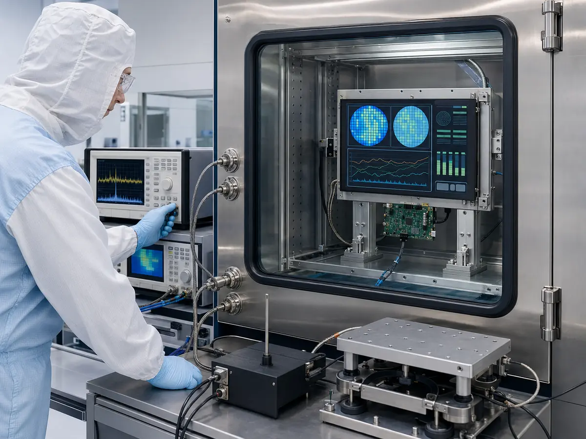
Display approval should be based on a staged validation process. Datasheet comparison helps identify candidates, but it cannot reproduce software behavior, enclosure temperature, touch noise, optical reflections, or long-term operating conditions.
What Should Be Checked During Datasheet Review?
Engineers should compare active area, outline dimensions, mounting structure, resolution, aspect ratio, pixel density, interface, connector, pin definition, power voltage, current, backlight design, brightness, contrast, viewing angle, operating temperature, storage temperature, backlight life, surface treatment, and product status.
Datasheets should be kept with revision numbers. If the supplier changes a controller IC, polarizer, LED, or production location, the equipment manufacturer needs a clear reference for determining whether the change affects qualification.
What Should Be Tested on the Engineering Bench?
The first sample should be operated with the intended host computer or controller. Engineers should verify native resolution, image stability, color format, refresh rate, brightness control, touch communication, startup timing, power sequence, signal-loss recovery, sleep recovery, and repeated power cycling.
Test patterns can reveal dead pixels, mura, line defects, grayscale problems, color irregularities, and image retention. The complete HMI software should then be reviewed rather than relying only on test images.
What Should Be Tested After Installation?
The display should be installed with the final cover glass, touchscreen, gasket, housing, cables, controller board, and power supply. Engineers should run the machine through representative operating cycles while monitoring temperature and touch behavior.
Viewing should be checked from the expected operator positions. Reflections should be evaluated under actual facility lighting. If the machine supports multiple languages, each interface version should be reviewed for text clipping and incorrect scaling.
Touch testing should cover gloves, corners, edges, dragging, rapid taps, long presses, and gestures. Any critical command should be checked for accidental activation risk.
Which Environmental and Electrical Tests Are Necessary?
The test plan may include high- and low-temperature operation, thermal cycling, continuous operation, vibration, ESD, EMC, repeated cleaning, humidity exposure, and power interruption. The exact test level should match the machine’s application and customer qualification requirements.
Testing should use the final cable routing and grounding structure. Moving a cable or controller board during production can change electromagnetic performance even when the panel model remains the same.
How Should Acceptance Criteria Be Defined?
Acceptance should be based on measurable criteria. Examples include permitted pixel defects, brightness range, uniformity, touch accuracy, startup time, maximum temperature, viewing performance, surface condition, and correct operation of every software page.
Incoming inspection should distinguish between panel-manufacturer criteria and equipment-level criteria. A panel can meet its factory specification while still being unsuitable for the customer’s final HMI.
How Should Long-Term Availability Be Evaluated?
Engineers should review whether the panel belongs to an industrial product family, how long it has already been in production, whether the manufacturer provides product-change notices, and whether similar alternatives exist.
The approved display record should include the LCD model, revision, controller board, firmware, cable, touch controller, cover-glass drawing, bonding structure, software resolution, and validation results.
A second option should be identified where practical. It does not always need to be fully qualified at the beginning, but its mechanical and electrical differences should be understood before the original panel becomes unavailable.
For a detailed lifecycle discussion, see Why Is Long-Term Availability Critical in Semiconductor Manufacturing Equipment?.
When Should the Display Be Released for Production?
Production release should occur only after electrical, mechanical, optical, touch, thermal, software, environmental, and lifecycle requirements have been reviewed. The approved configuration should receive a controlled part number or revision.
Sample approval should also define which changes require customer notification or renewed testing. Without change-control rules, a substitute cable, controller firmware, touch IC, or panel revision may enter production without the engineering team understanding its effect.
Claim: Semiconductor displays should be validated from datasheet review through bench testing, installed-equipment testing, environmental evaluation, and lifecycle assessment. Production approval must apply to the complete, documented display configuration.
5. What Advantages Does XIANHENG Offer for Semiconductor Machine Display Projects?
XIANHENG supports semiconductor equipment manufacturers with industrial LCD selection, touchscreen customization, display integration, replacement evaluation, and lifecycle planning. Our role is not limited to supplying a panel model. We can help customers convert equipment requirements into a practical display assembly.
Which Industrial LCD Options Can XIANHENG Provide?
XIANHENG can support industrial TFT LCDs from established manufacturers such as BOE, AUO, Innolux, and Tianma. Available options include TN, VA, IPS-type, ADS, and AHVA panels with different sizes, resolutions, brightness levels, viewing angles, interfaces, and operating-temperature ranges.
Industrial displays from approximately 7 inches to 55 inches can be evaluated according to the equipment structure and HMI requirements. Customers can review available models through the Industrial LCD Product Collection.
How Can XIANHENG Support Touchscreen Customization?
We can provide projected capacitive or resistive touch solutions. Customization can include sensor dimensions, cover-glass size, thickness, printed border, logo, transparent windows, surface treatment, touch interface, cable length, and controller firmware.
For PCAP applications, touch performance can be developed around the intended cover glass, gloves, grounding, and enclosure. Optical bonding is available for projects requiring lower internal reflection, improved perceived contrast, or a sealed optical gap.
How Can XIANHENG Support Display Integration?
Depending on the project, XIANHENG can support the standalone LCD panel, TP plus LCM assembly, customized cables, HDMI or other controller solutions, open-frame display, touch monitor, or integrated HMI display assembly.
Our engineers can review mechanical drawings, interface requirements, connector positions, cable routing, power conditions, touch structure, and cover-glass design before samples are prepared.
How Can XIANHENG Support Replacement Projects?
For an obsolete or unavailable display, customers can provide the original panel model, datasheet, photographs, cable information, enclosure dimensions, software resolution, and touchscreen requirements.
We can compare possible replacements according to active area, outline, mounting, resolution, interface, connector position, voltage, brightness, viewing angle, backlight, timing, and temperature range.
If no true drop-in replacement is available, we can identify which cables, controller boards, brackets, touchscreens, or cover-glass components need to change. This provides a more reliable basis for equipment qualification than selecting a panel according to size alone.
How Can Customers Request a Display Recommendation?
To receive an accurate recommendation, customers should provide the required size, resolution, interface, brightness, touch type, operating temperature, viewing direction, annual quantity, equipment function, expected lifecycle, and available mechanical drawings.
To discuss a new semiconductor equipment HMI, wafer inspection monitor, customized touchscreen, optical-bonded display, or obsolete-panel replacement, please reach out to XIANHENG.
Claim: XIANHENG helps semiconductor equipment manufacturers select and integrate industrial displays by combining LCD sourcing with touch customization, optical bonding, controller and cable support, replacement evaluation, sample validation, and lifecycle planning.


