
Mining display vibration and shock requirements should start at the point where the screen attaches to the machine. A haul truck crossing a rough ramp, a drill working through changing rock conditions, and a crusher control station mounted on a steel structure do not deliver the same mechanical input to an HMI.
The practical failure is often intermittent. The screen flickers during travel, touch disconnects when drilling starts, or a camera image freezes after an impact. The assembly may look undamaged afterward. Finding the cause requires following the load from the machine structure through the console, bracket, glass, electronics, and cables while monitoring what the operator actually sees.
Quick Answer: Mining displays need vibration and shock qualification matched to their mounting location and operating duty. There is no universal mining requirement expressed by one acceleration value. Specify vibration frequency content, amplitude or power spectral density, duration, axes, mounting, and operating state; specify shock pulse shape, peak acceleration, duration, direction, and event count separately. Test the production display, bracket, touch-and-glass stack, controller, connectors, and cables as installed. Acceptance should cover structural integrity, continuous image and touch operation, communication, and defined fault recovery.
Claim: Mechanical qualification belongs to the installed display load path and its required functions, not to a bare LCD acceleration rating.
1. Which Mining Events Should Define the Mechanical Input?
Divide the duty cycle into events before selecting a laboratory profile. Engine operation, travel, loading, drilling, processing, parking, and transport can produce different inputs even on the same machine.
Direct answer: Identify the events that load the display mounting points, measure or otherwise justify their severity, and translate them into separate vibration and shock requirements. Include the expected duration and repetition rather than recording only the largest observed peak.
What Should Be Captured During Haul-Truck Travel?
Road condition, speed, payload, suspension state, tire condition, and console location can change the motion reaching a cab display. Empty return travel may differ from loaded travel, and braking or crossing a road discontinuity can create distinct events.
Collect data at relevant attachment points and document the machine state. Measurements on the chassis should not be transferred unchanged to a display inside a suspended cab without reviewing the intervening structure.
How Does Drilling Change the Input?
Drilling can combine sustained excitation with changes associated with feed, rotation, percussion where present, and rock conditions. A console that behaves well at idle may become unstable during a particular operating mode.
Record the modes represented by the data, including transitions into and out of work. A brief survey at one setting may miss the operating condition that excites a bracket or repeatedly flexes a cable tail.
Why Can a Fixed Crusher Station Still Need Mechanical Review?
A stationary HMI can receive vibration through a shared platform, support frame, cabinet, or floor. Its input depends on where it sits relative to machinery and how the mounting structure responds.
Compare equipment running, material feeding, and other credible production states. Moving the cabinet to a different steel member may change its input even when the display model, software, and electrical connection remain identical.
Which Shock Events Need Separate Treatment?
Discrete impacts may arise during loading, travel over discontinuities, handling, or another defined machine event. Their relevance depends on the installation; a portable service terminal also introduces drop and handling questions absent from a fixed panel.
Specify the event being represented and the appropriate procedure. A shock pulse applied through a mounted fixture does not automatically demonstrate free-drop resistance or packaged-shipping protection.
Why Is a Single g Value Incomplete?
For sinusoidal vibration, frequency, displacement or acceleration, sweep details, and duration matter. Random vibration requires a defined frequency range, power spectral density, overall level, and exposure time. Equal overall acceleration can conceal very different energy distributions.
Shock also needs pulse shape and duration alongside peak acceleration. A short pulse and a longer pulse with the same peak can produce different responses in the assembly. Directions, repetitions, and test mounting complete the requirement.
| Mining Event | Input to Establish | Function to Observe |
|---|---|---|
| Loaded and empty travel | Mounting-point vibration and discrete road events | Live data, camera image, backlight, and link continuity |
| Drilling modes | Mode-dependent frequencies and working duration | Guidance visibility, touch connection, and controller state |
| Crusher and conveyor operation | Cabinet input through the supporting structure | Alarm transitions, changing values, and cable behavior |
| Handling and transport | Relevant mounted, portable, or packaged condition | Retention, physical condition, and post-event operation |
Claim: The mechanical requirement should preserve the event, frequency content, duration, direction, and installation represented by the input.
2. How Does Machine Motion Become a Display Fault?
The display responds to motion through several connected structures. The cabinet and bracket may move differently from the LCD frame, while a cable tied to the cabinet can pull against electronics moving on another support.
Direct answer: Trace the load through the console, mounting hardware, glass, LCD frame, circuit boards, connectors, and cable restraints. Look for relative movement, concentrated stress, resonance, and changes in contact rather than assuming the LCD cell is always the cause.
Where Can a Console Amplify the Machine Input?
A bracket or panel can respond strongly near one of its natural frequencies. At that condition, motion at the display may exceed the motion at the structure used to control a laboratory test.
Review bracket span, thickness, attachment spacing, mass, and boundary conditions. A resonance survey can help identify the response, but acceptance still depends on its effect under the specified working profile.
How Can Glass Support Introduce Uneven Stress?
Large cover glass adds mass and needs support appropriate to its construction. Hard local contact, edge damage, excessive clamping, or insufficient clearance can concentrate stress as the assembly moves.
The LCD frame and bonded stack should follow their approved mounting guidance. A cover window should not transmit an uncontrolled load into the LCD cell merely because the completed front appears mechanically solid.
Why Can a Cable Create an Intermittent Image Failure?
A long unsupported cable section can move repeatedly, load a connector, or flex near a stiff termination. A cable restrained on one structure and plugged into another can also transfer their relative movement to the connection.
The symptom may be flicker, image loss, touch disconnection, or a power reset. Cable pinout and signal compatibility remain necessary, but they do not establish mechanical retention or flex life.
How Do Circuit Boards Enter the Failure Chain?
Controller boards, power converters, and backlight drivers have their own supports and component masses. Board flex, insufficient standoff support, or movement of attached hardware can affect electrical continuity.
Check how the actual board is mounted and where cables attach. A successful LCD component test does not cover a controller installed on a different plate or a power connection carrying additional harness weight.
Can the Display Remain Intact but Become Hard to Operate?
Yes. Relative motion between the operator, screen, and hand can make small text difficult to read or touch targets difficult to select. That is a usability problem even if the electronics never disconnect.
Review the seated sight line and supported hand position during representative machine motion. Physical-control allocation and touch feedback should follow the operating task, as discussed in How Do Touchscreens Improve Mining Equipment Operation?.
Claim: Intermittent display faults can begin anywhere along the mechanical and electrical load path, including structures outside the LCD itself.
3. Which Mounting Changes Reduce Risk Without Creating New Loads?
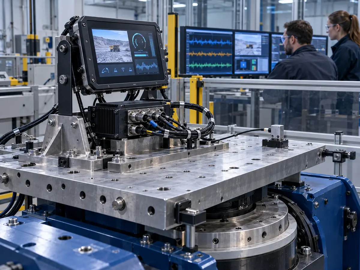
Adding stiffness, foam, isolation, or a cable tie changes how loads travel. Each change should solve an identified problem and be checked for its effects on displacement, stress, heat transfer, sealing, and service access.
Direct answer: Control support geometry and mass, restrain connections without overloading them, allow necessary material movement, and assess isolators against the actual frequency range. Verify the result in the installed configuration.
When Should the Bracket Be Stiffened or Repositioned?
If a flexible span amplifies motion, shorter spans, additional support, a revised section, or relocation may help. The change should be assessed against attachment loads and the machine structure that carries them.
A stiffer bracket can reduce one response while transferring more input at other frequencies. Measure the resulting behavior instead of assuming that maximum stiffness is always the best mounting choice.
When Can Isolation Make the Result Worse?
An isolator's behavior depends on stiffness, damping, supported mass, frequency, temperature, and available movement. Around its resonance, a poorly selected system can increase response rather than reduce it.
Allow clearance for credible travel and evaluate bottoming, aging, and changes in material properties. Cables and other attachments should not bypass the intended isolation path or restrain the assembly unpredictably.
How Should Connector Retention and Strain Relief Work Together?
Use the approved latch, lock, bracket, or retention method for the connection. Position strain relief so that harness loads are carried by the intended support instead of the connector contacts or circuit board.
Leave enough controlled flexibility for assembly movement and service, with suitable bend radius and abrasion protection. A tie placed immediately beside a termination can create a repeated bending point if the rest of the cable moves.
What Should Be Defined for Fasteners and Soft Supports?
Specify fastener type, engagement, tightening method, locking approach, and inspection where relevant. Foam and gaskets need defined material, thickness, placement, and compression rather than substitution by appearance.
Soft supports can creep or change with temperature and exposure. Their movement can alter glass support or seal pressure, so mechanical changes should be reviewed alongside enclosure protection and thermal requirements.
Why Does Service Access Belong in the Mounting Review?
A reliable assembly should permit replacement without forcing cables, damaging seals, or requiring uncontrolled fastener changes. Confirm the removal direction, tool clearance, connector access, and reassembly sequence.
Provide records for the approved bracket and cable routing. Otherwise, a field replacement can restore the correct electrical part while introducing an unsupported cable span or a different mounting preload.
Claim: A mounting improvement must address the complete load path and preserve the intended thermal, sealing, cable, and service conditions.
4. How Can Testing Capture Faults That Disappear When the Machine Stops?
A post-test photograph cannot show a temporary loss of video or touch during exposure. Qualification needs a way to observe operation continuously and connect a recorded fault with the mechanical event that preceded it.
Direct answer: Use a representative fixture, control and measure the relevant input, monitor changing image and input functions, record power and communication behavior, and inspect the assembly after exposure. Preserve the tested configuration and any recovery actions.
How Should the Fixture Represent the Machine?
Use the approved mounting points, bracket, fastening conditions, orientation, and representative attached mass. Evaluate fixture dynamics so that the test does not introduce an unrecognized resonance or suppress a relevant response.
Document where the input is controlled and where specimen response is measured. A rigid laboratory adapter and a flexible production console can produce different results from the same controller setting.
What Should the Running HMI Show?
Use changing values, timed image transitions, alarm states, and camera or moving content where applicable. A stationary picture can conceal frozen data, temporary link loss, or an application that has stopped updating.
Check touch communication and permitted input behavior separately. A test actuator or logging method should not mechanically support the specimen in a way that changes its response.
How Can Mechanical and Electrical Faults Be Separated?
Record relevant supply voltage, controller status, link events, touch enumeration, and timestamps alongside mechanical measurements. This helps distinguish a video-connection interruption from a host reset, power disturbance, or software failure.
Connection architecture remains part of the evidence. The signal paths are reviewed in What Display Interfaces Are Used in Mining Equipment?.
What Acceptance Criteria Should Be Agreed Before Testing?
Define permitted image artifacts, information-update behavior, touch continuity, resets, communication faults, physical damage, and recovery. For required functions, state whether any interruption is allowed and how unavailable or invalid information must be indicated.
A unit that resumes after manual power cycling has not necessarily met the requirement. Preserve the interruption and intervention in the result even if the final image looks normal.
What Should Be Inspected After Exposure?
Inspect fasteners, bracket alignment, connector locks, abrasion marks, cable bends, glass edges, LCD condition, board supports, and seals. Compare baseline image, brightness, touch mapping, and startup behavior.
Where the qualification plan requires it, check sealing or thermal performance after mechanical exposure. Such combined evidence should be explicitly planned; it is not automatically included in a vibration or shock rating.
Which Changes Require an Evidence Review?
Review changes to LCD or glass mass, bracket geometry, isolators, fasteners, foam, bonding, controller mounting, connector type, cable length, or restraint position. Even an electrically compatible replacement can change mechanical response.
The responsible equipment organization should determine which tests or assessments must be repeated. Broader configuration responsibilities are described in Why Does Mining Equipment Need Industrial LCD Displays?.
Claim: Mechanical approval requires evidence of function during exposure, recorded recovery, and inspection of the production load path afterward.
5. What Advantages Does XIANHENG Offer for Mining Display Mechanical Projects?
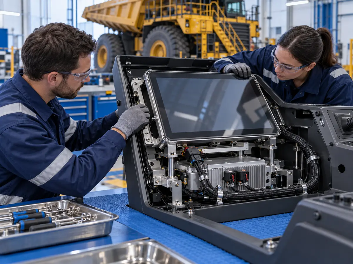
XIANHENG supports display integration for mobile-machine consoles, drilling controls, processing stations, maintenance tools, and replacement projects. Work can begin with a new mounting arrangement or an existing installation showing intermittent image or touch faults.
Direct answer: XIANHENG can coordinate LCD selection, touch, cover glass, bonding, mechanical drawings, controllers, cables, samples, and replacement comparison. Final machine load definition, mounting approval, equipment safety, hazardous-location assessment, and qualification remain with the responsible manufacturer and assessment parties.
How Can Candidate LCDs Be Compared Mechanically?
Compare panel outline, thickness, mounting features, mass, connector location, cable direction, and supplier test conditions alongside optics and electrical requirements. Any component-level vibration data should retain its stated mounting and operating limitations.
Starting models can be reviewed in the Industrial LCD Product Collection. Selection should match the intended assembly rather than rely on the word industrial alone.
Can Glass, Touch, and Cables Be Coordinated?
Supported development can align cover-glass outline, viewing area, touch tail, bonding construction, frame clearances, connector access, and cable routing. Drawings can identify support regions and the interfaces needing customer review.
Customized cables can define connector models, pinout, length, direction, shielding, and retention details. The equipment test still needs the actual harness restraints and movement conditions.
How Can Samples Help Investigate an Intermittent Fault?
A representative sample can include the intended LCD, touch stack, glass, controller, firmware, and cable set. Initial checks establish image operation, touch mapping, startup, and delivered configuration.
The customer can test it with the production bracket and host while recording faults during exposure. Findings should include machine state, input data, mounting, symptoms, and recovery so that supported display-side revisions address a defined cause.
What Should Be Supplied for Replacement Analysis?
Provide original models, datasheets, mounting drawings, glass and bracket dimensions, cable routes, controller information, fault logs, and a working sample where available. Identify whether failures occur during travel, drilling, impacts, or a particular machine speed.
XIANHENG can compare candidate solutions across mechanical, optical, electrical, firmware, and lifecycle differences. Approval should review the affected load path and tests before a substitute enters production or service.
What Information Should Customers Send to Start?
Useful inputs include equipment type, display position, mounting drawings, measured vibration and shock data, operating events, glass construction, host, cables, restraints, temperature, required functions, acceptance criteria, quantity, schedule, and service-life target.
To discuss a haul-truck display, drill-rig touchscreen, crusher HMI, mechanically integrated LCD assembly, customized cable set, or replacement project, please reach out to XIANHENG.
Claim: XIANHENG supports mining mechanical projects by coordinating display-side components, drawings, cables, and samples around the customer's documented load path and qualification plan.


